The Engineering Conflict: Pole Spacing vs. Longitudinal Uniformity
In municipal roadway and infrastructure lighting, luminaire design is governed by strict regulatory frameworks, such as the IESNA RP-8 in North America or EN 13201 in Europe. These standards dictate specific requirements for average road surface luminance, overall uniformity, and the strict limitation of disabling glare.
For structural engineers, urban planners, and luminaire manufacturers, the primary economic driver of a street lighting project is the pole spacing. Maximizing the distance between lighting columns drastically reduces the total capital expenditure of the project by minimizing the number of poles, concrete foundations, underground trenching, and copper cabling required.
However, pushing poles further apart introduces a severe optical conflict. As the distance increases, the luminous flux struggles to reach the midpoint between the luminaires. This creates a dangerous photometric failure known as the “zebra effect”—alternating bands of high illuminance directly under the pole and dark, low-visibility zones in between. Attempting to bridge this dark gap simply by increasing the lumen output or elevating the angle of a basic lens invariably creates high-angle candela intensity, which manifests as blinding glare for approaching drivers. Resolving this conflict requires abandoning generic optics in favor of highly specialized, asymmetric secondary lens arrays.
Breaking Symmetry: The Geometric Failure of Circular Optics
A persistent error in low-cost outdoor lighting design is the reliance on symmetric optical distributions. Basic flat diffusers or standard circular lenses with 90° or 120° beam angles are fundamentally incompatible with roadway geometry.
Street lighting poles are almost universally positioned at the edge of the target area, not the center. When a symmetric 120° optic is mounted on a roadside pole, the light distribution is split evenly into a circle. While the front half of the beam covers the roadway, the rear half of the beam is projected directly behind the pole. From an engineering perspective, this “house-side spill” represents a massive loss of efficiency. Up to 50% of the luminaire’s consumed energy is wasted illuminating adjacent grassy berms, sidewalks, or residential facades, contributing heavily to light trespass and environmental light pollution.
To maximize the Utilization Factor (UF)—the percentage of total lamp lumens that actually reach the target roadway—engineers must specify optics that actively break this symmetry. This is achieved through computer-aided freeform optical design. By molding complex, asymmetrical curvatures into the surface of the polycarbonate (PC) or PMMA lens, the optic captures the rearward-emitting photons and refracts them forward into the street, while simultaneously stretching the beam laterally along the direction of traffic.
The Engineering Solution for Two-Lane Roads: Type II Distribution
The Illuminating Engineering Society (IES) categorizes street lighting distributions into specific types based on how far the light is pushed forward across the road and how widely it is spread laterally. For standard two-lane municipal roads or wide pedestrian walkways, the most commonly specified photometric footprint is the Type II distribution.
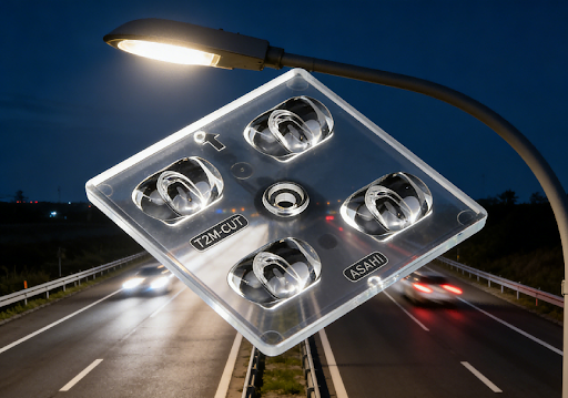
Achieving a true Type II distribution requires precise photon management, particularly when utilizing high-efficacy, high-power LEDs. Luminaire designers frequently resolve this specific geometric challenge by integrating specialized multi-lens arrays directly onto their LED boards. A prime example of this engineering approach is the specification of arrays like the 2×2 Type II M Street Light Lens.
Designed specifically to accommodate larger 5050 LED package sizes, this 2×2 modular array utilizes freeform asymmetric cavities to execute a Type II Medium (Type II M) distribution. The “Medium” designation indicates that the lens is engineered to project the maximum candela point to a specific lateral distance, allowing engineers to achieve wide pole spacing without creating central dark spots. Crucially, the internal geometry of this specific lens type is designed to abruptly halt the backward projection of light, securing a sharp cutoff on the house-side and ensuring that the vast majority of the luminous flux is directed precisely onto the asphalt.
The Physics of Glare Control: Managing High-Angle Candela
While pushing light laterally along the road solves the uniformity issue, it introduces the most critical safety hazard in roadway lighting: glare.
When an optic attempts to throw light a long distance to reach the next pole, it must emit light at a high angle relative to the nadir (straight down). However, light emitted between 75° and 90° aligns directly with the windshield viewing angle of an approaching driver. A high candela intensity in this specific angular zone causes pupillary constriction and temporary blindness, significantly increasing the risk of accidents.
To evaluate a luminaire’s ability to control this stray light, engineers rely on the BUG rating system, which quantifies Backlight, Uplight, and Glare. To achieve a favorable BUG rating and comply with “Dark Sky” initiatives, the secondary optic must be engineered with a strict physical cutoff. This means the lens micro-structure must totally internally reflect or refract any stray light rays that attempt to exit the fixture above the 80° threshold, ensuring a safe, comfortable visual environment for motorists.
Structural Integration of High-Wattage Arrays
When illuminating wide arterial roads or multi-lane highways, lighting engineers must specify high-wattage luminaires. This requires larger metal-core printed circuit boards (MCPCBs) densely populated with high-power LEDs. Historically, these large LED engines were protected by a flat tempered glass visor and sealed with a perimeter rubber gasket. This legacy structural design is heavy, prone to assembly errors, and creates a secondary optical interface that traps heat and reduces overall light transmission.
Modern luminaire design eliminates the glass cover entirely by utilizing large-format, modular multi-lens arrays. For high-lumen streetlights, structural engineers frequently specify high-density optical arrays such as the IP66 Street Lighting 3×8 Lens. Designed specifically for 5050 LED packages, this expansive 24-lens module maintains the strict Type II Medium cutoff required for glare control while simultaneously acting as the primary environmental seal for the luminaire.
By integrating a continuous silicone gasket groove directly into the back of the polycarbonate molding, the lens compresses firmly against the aluminum heat sink, achieving a reliable IP66 or IP67 ingress protection rating. This direct-seal method drastically simplifies the factory assembly line, reduces the luminaire’s overall weight, and maximizes the thermal dissipation of the LED board by removing the insulating air gap caused by traditional glass covers.
Rectangular Distributions for Aisle and Pathway Geometries
While wide asymmetric distributions are ideal for municipal roads, engineers encounter entirely different geometric constraints when designing for narrow industrial exterior aisles, pedestrian tunnel pathways, or linear high-bay environments.
In these highly restricted spatial corridors, deploying a standard street lighting optic—even a narrow Type II distribution—will result in severe optical waste. The light will spill uselessly up the vertical walls of adjacent buildings or racking systems, failing to illuminate the ground. To resolve this, the photometric distribution must be aggressively compressed into a strict rectangular footprint.
This requires optical modules engineered with extreme asymmetric beam angles, typically in the range of 30°x110°. A highly effective structural solution for this specific spatial geometry is the 173mm 2×6 LED Lens 30×110.
The tight 30° transverse angle strictly limits lateral light spill, keeping the photons off the walls, while the wide 110° longitudinal angle pushes the light far down the corridor to maintain wide fixture spacing. Furthermore, the physical 173mm linear footprint of this 2×6 module is specifically engineered to integrate seamlessly into the slim, extruded aluminum profiles favored in modern linear high-bay and architectural pathway lighting designs.
Conclusion: Optical Efficiency and Total Cost of Ownership (TCO)
In the highly competitive landscape of municipal tenders and large-scale commercial lighting projects, the specification of the secondary optical system is the primary determinant of a luminaire’s Total Cost of Ownership (TCO). The absolute lumen output of the LED chip is irrelevant if the optical array cannot efficiently direct those lumens precisely to the target plane.
By specifying precision-engineered, modular multi-lens arrays—whether utilizing Type II distributions with strict cutoff for roadways or 30°x110° profiles for industrial aisles—manufacturers maximize the luminaire’s Utilization Factor. This high optical efficiency yields compounding systemic benefits: it allows engineers to specify lower-wattage LED drivers to hit target lux levels, reduces the required surface area of the aluminum heat sink, and ultimately lowers the structural weight on the lighting pole.
By prioritizing advanced freeform optics and integrated IP66 sealing mechanisms, luminaire designers guarantee superior photometric compliance while securing a definitive economic advantage in project bidding and long-term infrastructure operation.